Start with the 555 timer design in CopperKit, choose the single-sided workflow, and walk through the tools and materials used for the whole build. This introduction explains how the later steps fit together.
At the workbench
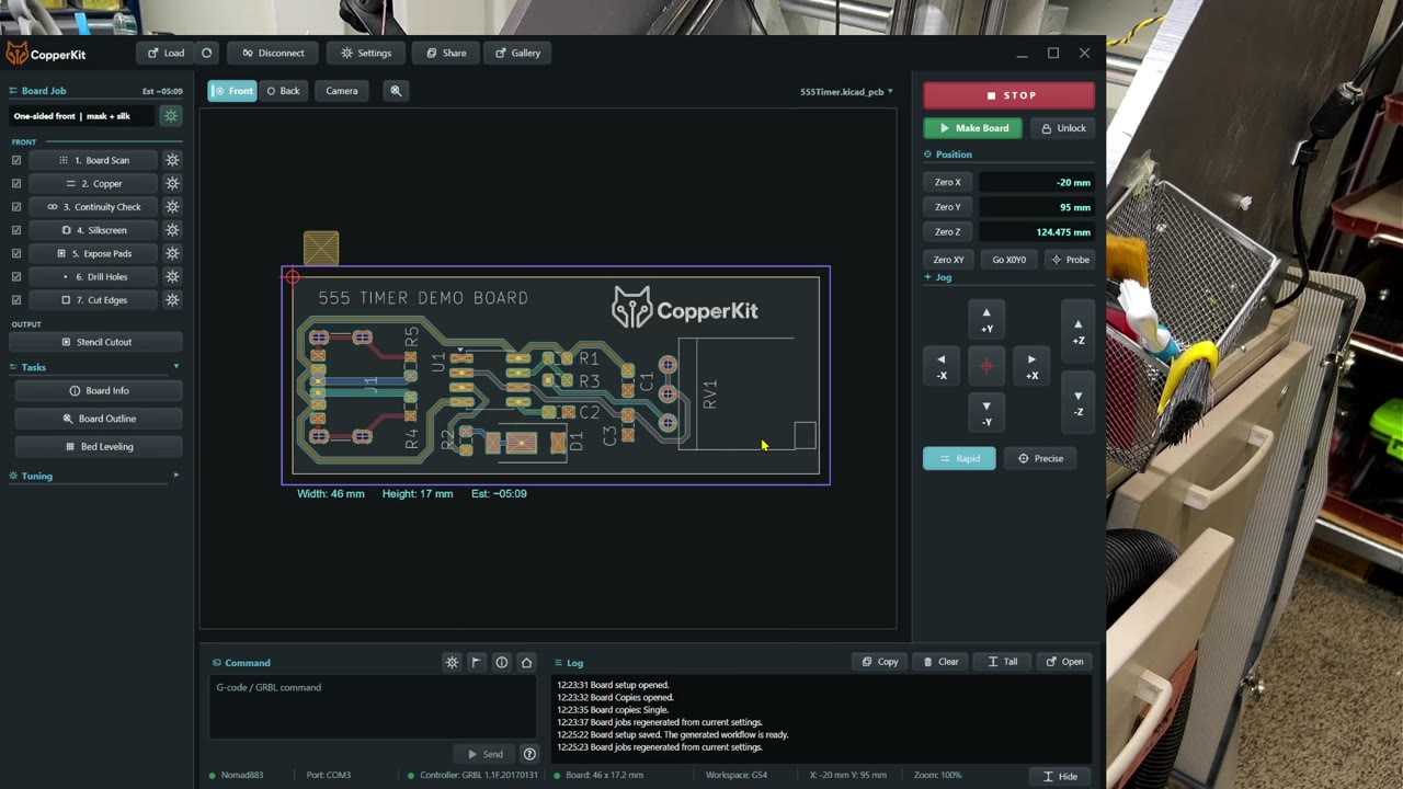
Load the board design and choose a single-sided workflow. Review the board placement, copper-cutting method, mask and silkscreen, drilling, and edge-cut options.
Gather the copper-clad blank, workholding materials, probe connection, stationary scriber, drills, and outline cutter before starting.
Prepare the mask, clear primer, transparency film, glass, UV lamp, paint, and cleaning supplies if you are following the full finish shown here.
Review your machine's cutting recipe. Depths, spacing, feeds, and tool choices need to suit your material and machine.
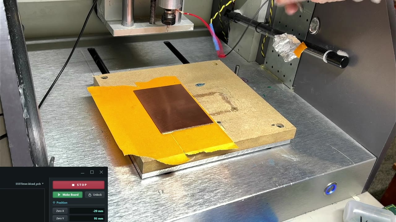
Hold the blank flat with painter's tape and superglue, then make a reliable electrical connection for probing. The demonstration also shows how a larger blank can leave room for subsequent boards.
At the workbench
Cover the underside of the blank with smooth painter's tape. Avoid wrinkles, trapped air, and unsupported edges; put matching tape on the wasteboard.
Apply glue between the taped surfaces, including the corners and edges. Press the blank flat and let the adhesive set before machining.
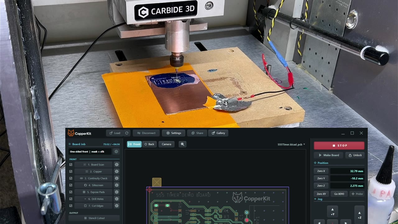
Connect the probe to the tool and copper. The demonstrated foil contact sits outside the cutting area.
Test the connection and confirm that CopperKit's probe indicator changes before starting a probing move.
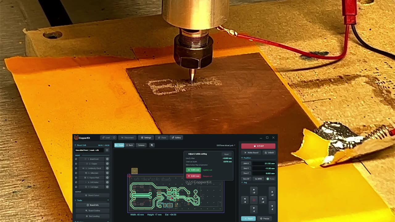
Position the job, probe the board surface, and isolate the traces with the spindle off. After cleaning, use the electrical checks to identify cuts that need another pass, then check the result again.
At the workbench
Choose the job's starting corner and confirm that the entire outline fits on the blank. Review the run mode and cutting recipe in Make Board.
Confirm the probe connection and run the surface scan. This build uses a stationary scriber with the spindle off for trace isolation.
At the cleaning pause, remove debris and burrs. Cleaning can change the isolation result, so run the electrical checks afterward.
Recut the indicated tracks or repeat the isolation pass as needed. Clean gently and check again before covering the board with mask.
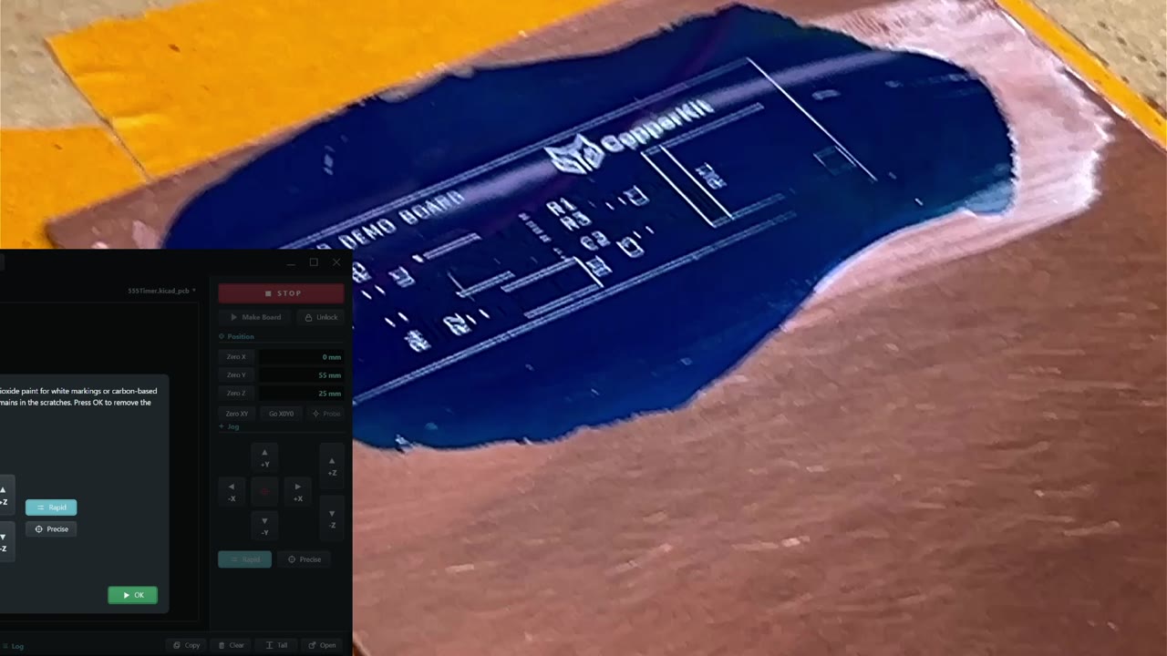
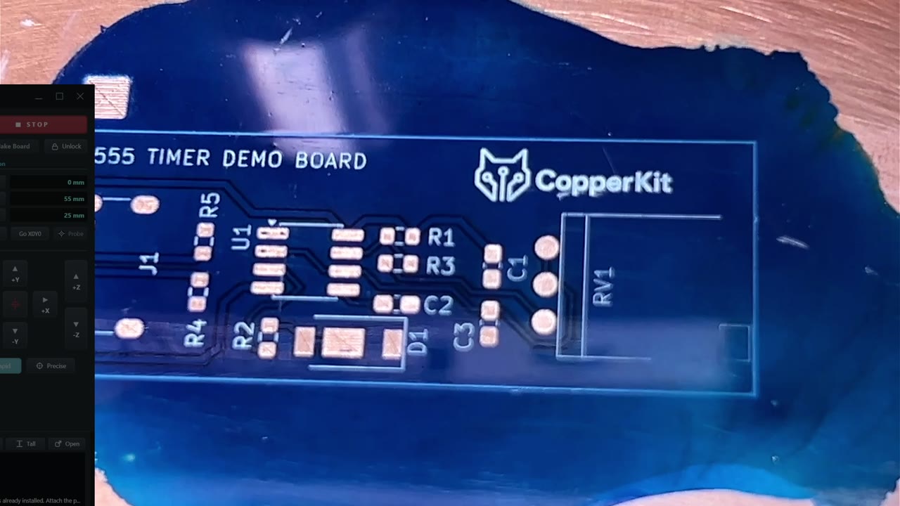
Apply a thin clear primer, spread the blue UV solder mask under transparency film, and flatten it with glass. CopperKit then engraves the markings into the cured mask, ready to fill with white paint.
At the workbench
Start with clean, prepared copper. Work a very small amount of clear mask into the surface as primer, remove excess, and briefly expose it as demonstrated.
Spread the colored mask under clean transparency film. Work out bubbles, cover the whole board outline, and press flat with glass.
Cure the mask with the film covering its surface. Confirm that it is firm enough for engraving; exposure depends on the resin, lamp, pigment, and layer thickness.
Run the silkscreen engraving. Fill the grooves with white acrylic paint and wipe the surface clean, leaving paint in the lettering.
Remove the mask from the pads with the stationary scriber. The close-up shows the shallow outline and interior clearing passes, plus the separate copper pad used to measure tools in the next stage.
At the workbench
Run Expose Pads with the board still fixed in place. Keep the spindle off for the stationary-scriber method shown here.
Watch the outline and interior clearing passes. Adjust depth and spacing to remove the mask and primer while preserving the copper.
Remove the debris and inspect the pads for remaining coating. Keep the separate tool-probing pad clean for the drill and end-mill changes.
Change to the requested PCB drills, measure each tool on the cleared probe pad, and drill the holes. Then fit the outline cutter, mill the perimeter, lift out the board, and finish its edges.
At the workbench
Fit the drill requested by CopperKit. Attach the probe and follow the prompts to measure the tool on the cleared copper reference pad.
Remove the clip from any rotating part before approving spindle start. Repeat the tool-change and measurement process for each drill size.
Fit the outline cutter and confirm its actual diameter, board thickness, and pass settings. Measure the tool, remove the rotating-part probe clip, and run the cut with appropriate dust collection.
After the machine stops, gently release the board from the tape. Remove backing tape, smooth the edges, and inspect the finished bare board.
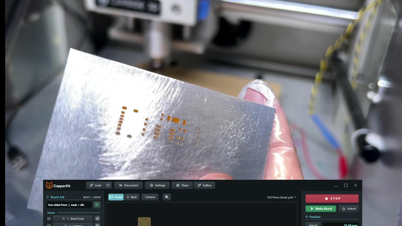
Generate the stencil from the same board design, mount a piece of aluminum flashing, and cut its apertures with overlapping plunge operations. While it runs, take a tour of CopperKit's tuning, sharing, and workflow controls.
At the workbench
Open Stencil Cutout, choose the orientation, and review which pads to include. Including through-hole pads is an optional experiment discussed in the video.
Secure the thin aluminum flat on the wasteboard. Check that it cannot lift or shift during the repeated plunges.
Set up the stencil tool and probing connection, position the job, and measure the surface. Clear the probe clip from rotating parts before starting.
Run the aperture pattern, then remove and inspect the stencil. Deburr the openings and check that each aperture is clear before applying solder paste.
Before you start
Supplies & tools
Materials used or discussed in this build. Choose tools and cutting settings for your own machine.
Supplies for the single-sided 555 board tutorial
Stage
What to have ready
Design & machine
CopperKit, the 555 board design, a compatible desktop CNC with a spindle for drilling and outline cutting, and a working electrical probe connection. The recording uses a Carbide 3D Nomad.
Blank & workholding
Single-sided copper-clad board (Bakelite/phenolic in this demonstration), a flat wasteboard, painter's tape, superglue, a tape-trimming knife, and foil for the demonstrated copper probe contact.
Cutting tools
A stationary carbide scriber that fits the machine's collet, PCB drills matching the design, and an end mill suitable for the outline and any slots. The outline cutter shown is 1.5 mm.
Surface preparation
A vacuum or suitable dust collection, a scouring pad or brush, fine abrasive paper, isopropyl alcohol, and lint-free wipes.
Mask & markings
Clear UV-curable mask for the primer, colored UV solder mask, a compatible UV lamp, clean transparency film, smooth-edged glass, a plastic card for spreading, and white titanium-dioxide acrylic paint.
Stencil
Thin aluminum flashing, low-tack tape and glue for holding it flat, a suitable short stencil-cutting tool, and fine abrasive paper for deburring.
Use the machine, adhesive, resin, and lamp manufacturers' handling and protection guidance. This is a process-supplies list; electronic components, solder-paste application, and reflow are outside these seven recordings.
Keep beside the machine
The build at a glance
Load and review the single-sided job, tools, and board placement.
Mount the blank flat and verify the probe connection.
Scan the surface, isolate the traces, clean, and check. Recut and recheck where necessary.
Apply primer and mask, cure, engrave the markings, and fill them with paint.
Clear all solder pads and the tool-probing pad; inspect the copper.
Measure each drill and cutter. Remove the rotating-part probe clip before spindle start, then drill and cut the outline.
Release and inspect the bare board. Make, deburr, and check its stencil.
These notes condense the demonstrated process. Use CopperKit's prompts and your own verified cutting recipe for exact settings. The recordings show real adjustments and imperfect areas, including a corner with incomplete mask coverage.

 Video coming soon